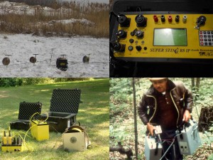
A resistivity test or an earth resistivity survey
is used for measuring soil ground resistance or earth resistivity imaging.
In addition to earth resistivity meters and soil ground resistance instruments, K.D. Jones Instruments has a wide assortment of geophysical equipment to rent.
Soil resistivity testing, ground resistivity testing, and a ground resistance test
are common geophysical methods used to assist engineers
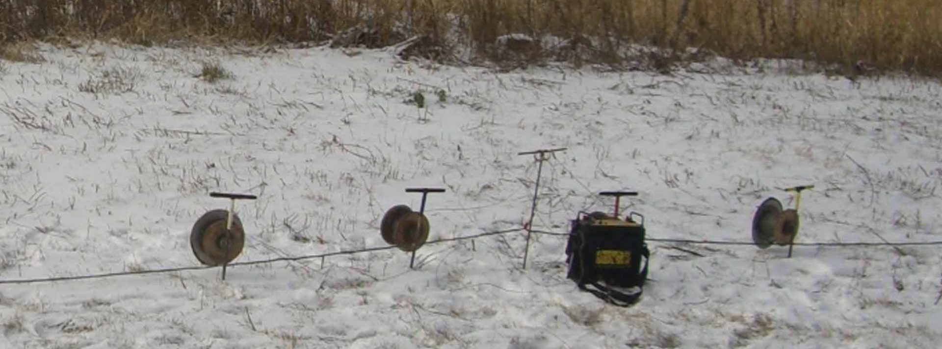
with how well electrical currents flow through the earth. While cathodic protection is often a concern for pipelines, the electrical power service industry utilizes an electrical resistivity test for designing earth ground systems. Grounding systems are designed into power plants, substations, electrical transmission lines, wind farms, radio towers, and a wide variety of other industries. Ground testing or resistivity test methods may include clamp on, four potential, star delta, 61.8% rule, fall of potential, simplified fall of potential, slope, and intersecting curves. The method of choice is often determined by an engineer who factors in the size and design of the grounding system. Many of these types of tests are conducted using relatively small and portable instruments. However, this category of instrumentation may not be able to deliver the power or current to acquire measurements with electrodes spaced at great distances apart. Sometime electrodes are spaced 1000’s of feet apart. At great distances measurements may be noisy or not repeatable without a resistivity meter that can deliver 1000’s of milliamps of current.
A complex earth resistivity imaging survey
yielding apparent electrical resistivity measurements
is a geophysical method used to characterize, map, or image the subsurface. This level of effort is more complex then a basic resistivity test. 2-D and 3-D geophysical representations of the earth often assist geologists, engineers, mining operations, and archaeologists with visualizing the subsurface. Today, intense Wenner, Wchlumberger, dipole-dipole, pole-dipole, and pole-pole multi-electrode earth resistivity surveys are conducted. These surveys acquire 1000’s of apparent resistivity measurements (follow this link to find resistivity imaging equipment). The type of survey and the spacing of the electrodes, in part, control depth of investigation, the resolution, and the time required to acquire the data. The resistivity data is inverted and modeled with sophisticated software to provide an image of the subsurface. However, one should be aware that these representations, as with any modeled results, are not unique. At times, it may be better to consider other engineering geophysical methods.


One thought on “Soil Resistivity Test and Earth Ground Resistance Meters”
Leave a comment or a question.
Comments are closed.